Bolted joints are familiar components encountered every day. But do you understand how they work? I’ll be the first to admit I didn’t. I’m still learning the complexities of them. For bolts, my basic assumption was they just needed to be tightened down. In this article, I would like to explain pre-tension or more commonly called pre-load. That preload is the tightening of a bolt.
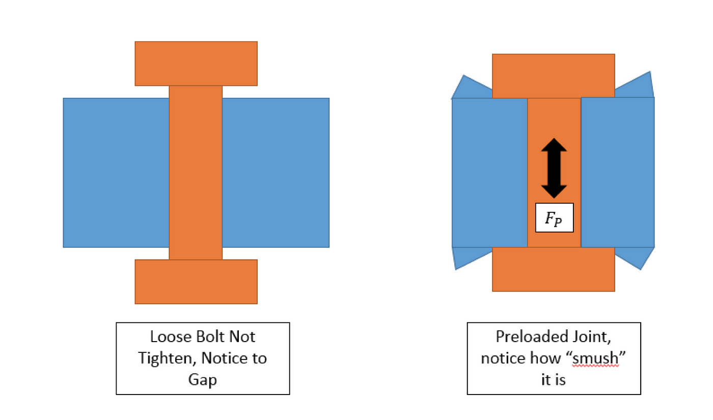
Let us begin by briefly explaining preload. Preload results by applying a certain amount of torque to tighten a bolt. That tightening causes the external threads to dig into the internal material’s threads. Tightening puts the bolt in tension. A plate is usually sandwiched between the bolt. The plate does not allow the bolt to penetrate through it. Therefore, a compressive reaction force is developed on the plate. That compressive force clamps down the joint, which is what you want. If you did not have any preload, the plate and the bolt would feel flimsy. A diagram of the preload and the induced forces is shown below.

The goal of preloading a joint is to prevent gapping. It is also used to increase the stiffness of the system. When you hand tighten a screw, there isn’t much preload. So it’s very easy for the component to gap.
To really understand and analyze bolted joints we have to think in terms of stiffness. The engineering term stiffness is defined as a force per unit displacement. For now, this article won’t go over how the stiffness of the bolt and the joint are calculated. The most important knowledge to take away is that the stiffness of the joint is usually much greater than the stiffness of the bolt. The diagram below illustrates how the bolt and joint are behaving from a stiffness point of view.

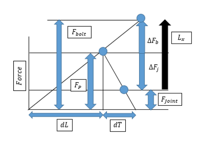
When preload is applied on the bolted joint, the bolt itself is undergoing tension. The joint is undergoing compression. For any bolted joint design, this is what’s desired. The graph below shows a force and displacement plot for both the bolt and the joint.
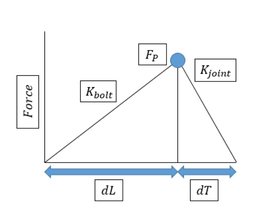
The slope of force vs displacement represents stiffness. Recall, the stiffness of the bolt is less than the stiffness of the joint. This is represented by the steepness of the joint’s slope being greater than the bolt’s slope.
The real fun comes in when there is an external load involved. For example, a lamp post can be bolted into the ground. It was a very windy day, which means there was some sort of external force being applied from the wind onto the bolts. The goal of the externally applied load is to separate the bolt from the ground. In other words, trying to gap the component.
The question we have here is how does the externally applied load impact the bolt? How much externally applied load is needed for the component to gap? Gapping occurs when there is no longer compressive forces on the component between the bolts. This is not good because it can lead to premature failure of a component.
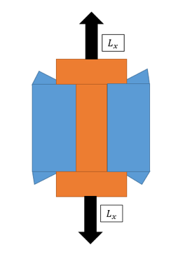
There are many ways an externally applied load can get into a part. We are going to make an assumption that an external tension load is applied to the bolt’s head and nut. Yes, this is a very simplistic assumption. But it’s going to help us breakdown the resulting behavior.
When an external load is applied, we need to analyze how much of that load gets distributed from the bolt versus the joint. When looking at how the load travels through a component, the load will always travel in the direction of the component with greater stiffness. When I first learned this, it was kind of confusing. Why would the load take the path of greater resistance, in this case more stiffness? We naturally think that nature wants to take the path of least resistance. The diagram below represents two springs in parallel, like the situation we have for the bolted joint, and an external load being applied.

One could imagine, that when you pull the structure most of that load will be carried to the stiffer spring. To understand why the load prefers the stiffer spring, we need to think in terms of energy. Since the blue spring is much stiffer than the orange spring, and they both have the same applied external load. The blue spring can store more energy per the same amount of displacement compared to the orange spring. This is the path of least resistance. The load would much rather store most of its energy in the stiffer spring because it’s more efficient. For a bolted joint, because the joint is more stiff than the bolt, more load would be taken from the joint than the bolt.
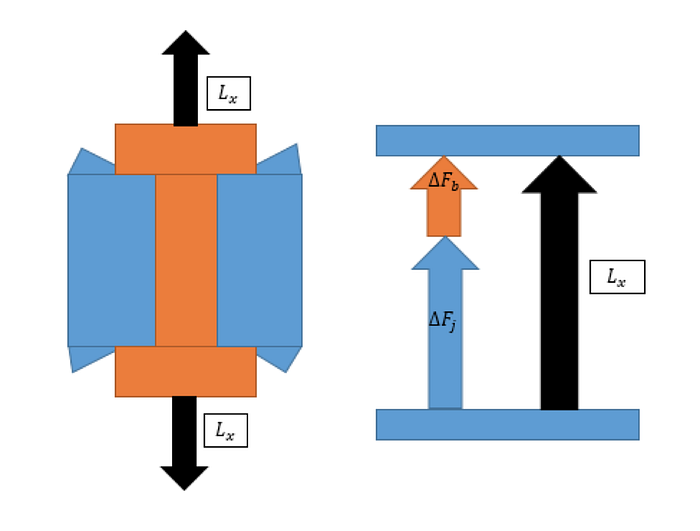
From a stiffness point of view the following is happening. The externally applied load is increasing the tension on the bolt, but a majority of that load is decompressing the joint. It’s reducing the compression forces on the plates. In other words, it’s making the connection become loose.

Here is an updated force and displacement diagram when an external load is applied. It illustrates that when an external load is applied, it reduces the compressive load on the plates due to preload. When you get to the point where there are no more compressive load on the plate the joint has gapped. Then all the load is carried to the bold, which is not good.